DUPS PS
by
Aron Levy
Technology Dynamics, Inc.
100 School Street. Bergenfeld, NJ 07621
Utility blackouts and brownouts are facts of life. Industry publications cite an average of 100 anomalies in utility power per month. The protection of sensitive equipment by the usage of AC stand alone UPS provides an easy solution, but as this article will show, this solution is far from being either cost effective or power efficient. An integrated DC UPS (DUPS) offers a substantially cheaper, more reliable and more efficient solution. However, this solution requires preplanning and serious consideration at the system design phase, while its power needs and sensitivity to power interruption must be clearly defined.
INTRODUCTION
On a daily basis and in thousands of places around the world, personal computers and workstations crash due to utility failures or merely a dip in their voltages. The crashes cause loss of data and system malfunctions. This results in a significant loss of time required to restore the information lost and to reset the system. Industry publications cite up to 100 utility malfunctions or disturbances per month in the U.S. In developing countries utility power is poorly regulated and very unpredictable – causing a constant nightmare to computer users.
Mass providers of telecommunication services and cable TV (as well as multitudes of other process-control industries) face the same exact problem. Here the problem results in the loss of customers and revenues. In process-control, a power failure could possibly cause the loss of irreplaceable material that would be destroyed if the operations process were to be interrupted. Imagine a blood analysis machine losing 100 blood samples due to a temporary malfunction caused by a utility failure. The inconvenience and wasted time to retake these samples is almost unimaginable. Now try to comprehend the crash of a computer in a stock market trading office or a busy airline reservation system, and you will quickly conclude that none of these systems should be operated without a power backup system which provides instant power replacement to utility. These backup systems are widely known as a UPS (Uninterruptible Power Source.) The length of backup time that the UPS provides depends on its rating, the capacity of its internal batteries, and on the magnitude of the load. Common backup time offered by most standard UPSs ranges between 5 minutes and 4 hours (but for the most part it is 5-15 minutes.)
In the vast majority of cases the design and cost to employ a UPS is left to the end user. This deprives the end user from a choice of options. Since he dares not redesign the systems (to include other means for backup,) he has no choice but to purchase a stand alone AC UPS and place it between the utility and the system. On face value, this seems to be an easy and straightforward solution, which will result in the satisfaction of both the user and (undoubtedly) the maker of the UPS. It is evident, however, that this is a fallacy. From an overall point of view, the use of stand-alone AC UPS does not result in a cost effective, high reliability or high efficiency solution to the backup problem. In fact, the overall efficiency of this arrangement is rather poor, and its cost burden is rather substantial. The maintenance cost of this inefficient system is ongoing, and for the duration of the system’s life cycle, it may add up to a sizable amount.
A far better solution is to satisfy the requirement for uninterruptible power by the use of a DC UPS (DUPS or USPS) within the system itself. However, this embedded approach requires that the system’s architect takes responsibility of either implementing the DUPS as part of the system design, or at least planning for such option should the need require its inclusion in the future. This approach pays well at the end in a more efficient, less costly and far more reliable system for the end user.
The main purpose of this article is to advocate the embedded DUPS approach or any form of a DC UPS in lieu of an AC UPS. The article further highlights a severe incompatibility problem (not known to most users) between AC UPS and Switchmode power supplies (SMPS). Consider that for external UPSs, the SMPS within the system is a highly non-linear load, which demands its current in high pulses, thus causing havoc within the UPS that feeds it.
This incompatibility problem is at the core of many unpleasant surprises to the end user, as he can connect an AC UPS to his system and as a result endure many unforeseen problems. These problems are related to the dynamics of the AC UPS and the SMPS within the host system.
A UPS PRIMER
Knowledge of the UPS and its performance attributes will contribute to the understanding of the complex issues at hand. It will also greatly assist in making the proper choice of UPS if the DUPS option cannot be used for one reason or another.
A UPS is a stand-alone unit containing a battery, a power inverter and control, and alarm circuitry. A classical UPS takes input utility (or generator) power and provides AC output voltage similar to the utility in terms of voltage and frequency. The size of the internal battery, as well as the UPS rating and conversion efficiency, determine the backup time when utility fails. Commonly, UPS equipment is rated in VA, (volt-ampere) not watts, because the load may contain a reactive component. The bigger the battery (in terms Ampere-Hour capacity) and the smaller the load, the longer resultant backup time will be. Often manufacturers specify backup time both at half load and at full load.
There are two major types of UPSs widely available in the consumer and industrial electronics markets. The first is labeled “Standby” or “Line-Interactive,” and the second is commonly called “On-Line” or “Double-conversion.” A brief description of the operational mode of these two types will now follow:
Standby-UPS
This type of UPS delivers the utility voltage as-is, (or after some conditioning,) to the output terminal (and from there to the load) via relay contacts or a solid-state switch. Once it is sensed that utility voltage failed (i.e. dropped below some threshold,) the relay transfers the load to an internal inverter, which converts the voltage of the internal battery to AC voltage of a similar magnitude and frequency to the utility. The battery now starts a slow discharge and its voltage gradually drops. If the utility voltage reappears quickly, the load is transferred back to it by the relay. However, if the utility blackout lingers, the battery discharges continuously until a certain predetermined threshold is reached, at which the time the control circuitry cuts off the UPS in order to avoid deep discharge of the battery. At this time, the load loses input power. Prior to that point, however, the alarm circuitry within the UPS alerts the user by visual alarms (usually red or blinking red LED,) and audio beeps (starting at 1 every few seconds and progressing to rapid beeps as the UPS reaches cut off. Also, relay contacts or electric signals are delivered to the user to facilitate orderly shut down. These alarm signals may be communicated to the host system via RS-232 or RS-485 communication protocol, thus enabling automatic control over the host system’s operation. Sophisticated UPSs provide a screen display (in an MS Windows environment) which appears on the host system monitor, advising the user how much time remains on battery. Some “Smart Software” is also available to program the orderly shutdown of the host system without human intervention – a useful feature if the system is unattended when power failure occurs.
The majority of Standby UPSs in the market provide a quasi square-wave AC voltage to the load. This allows a substantial cost reduction, since it is much easier to convert battery voltage (12V, 24V, or 48V) to quasi square-wave than to pure sinewave. This also contributes to making the unit smaller, lighter and more efficient, and does not seem to bother most computers.
Despite these advantages, however, the standby UPS suffers from a major disadvantage: The transfer of load from utility to internal inverter is made by relay, and therefore, there is a disruption of 5-10mS in current flow to the load. Fortunately, most personal computers (and some electronic systems) can tolerate such a disruption without a detrimental effect to performance. Therefore, millions of owners and users of PCs all over the world use inexpensive Standby UPSs.
On Line UPS
In this type of UPS, the internal inverter is actively working at all times and its output feeds the host system. As a result, the inverter must work non-stop (even when utility voltage exists.) In addition, On-Line UPSs usually provide pure sinewave voltage on their output terminals, and that obviously complicates its circuitry and adds to its volume and cost. Therefore, the price of an On-Line UPS is 3 to 5 times that of a standby UPS with the same power rating. The internal inverter runs on the battery continuously, and the battery is charged from a high power converter (charger) within the unit while running on utility voltage. Hence the frequently used name “Double-Conversion-UPS,”
A simpler method is to run the inverter on the rectified voltage of the utility. This makes the charger much smaller, since it only charges the battery (it does so slowly over 10-12 hours.) When utility drops, the battery takes over the DC rail, causing the operation of the inverter to continue without interruption. The two main features of the 0n-Line UPS are its sine-wave output and its true uninterruptible operation. Almost all of the On-Line UPSs in the market contain an output transformer, and hence provide galvanic isolation from utility- a highly desirable feature for safety and noise reduction.
On Line UPSs are made in a power range from 500VA to several hundred KVA. Most with internal batteries are adequate for 5-15 minutes of backup time during power interruptions. Some high-power units are equipped with a separate cabinet for the battery, and provide hours of backup time. When very long backup is required (12-48 hours) the battery bank becomes huge in size compared to the UPS itself, and a generator UPS may be a better choice.
Many On-Line UPSs are equipped with a Solid-State Transfer-Switch (SST,) which enables the transfer of the load to the utility if the UPS fails. This transfer also permits doing maintenance work on the UPS while the load is temporarily fed from the utility. A Phase-Lock-Loop (PLL) circuit within the UPS ensures “seamless” transfer of the UPS by the SST, between utility and inverter and vice versa. In terms of frequency and phase, the PLL circuit “locks” the UPS to utility at all times.
The main advantage of the UPSs (any kind) is in their being stand-alone units. As such, they may be added arbitrarily only to systems or loads that cannot tolerate utility interruptions. Therefore, the decision to use them is left to the end user and they become totally optional.
Their main disadvantage is that they are relatively expensive (especially On-line machines,) and their size, weight and power consumption are significant. Even though these costs and physical impacts are passed along to the host system (i.e. the end user,) this overall outlay and the continuous maintenance thereafter are to be considered as well. However, this is not the most severe disadvantage, as we shall shortly see.
The Compatibility Problem
Most end users are oblivious to the severe problems encountered when an On-Line UPS works with a non-linear load, such as a Switchmode power supply. Consider that the imbedded switchmode supply within the host system consumes its current in high magnitude pulses, and as a result overloads the UPS and distorts its output. On numerous occasions, a bitter dispute erupts between the end user and the UPS manufacturer. Here is a hypothetical example: The user claims that he has a 1000-watt SMPS in the system (i.e., a P.S. that provides the systems with 800W and consumes approximately 1000W from the line.) Therefore, he conservatively chose a 1500VA On-Line UPS and paid $1600 for it. However, when he plugged the host system (perhaps a computer or work station-both with SMPS) to the UPS and the UPS to the utility, alarms were heard, and the system’s performance seemed to be severely degraded in performance. Upset, the end-user blames the UPS manufacturer that the UPS is under-rated and weak. The maker, however, is willing to demonstrate unequivocally that his UPS produces a good sinewave voltage into a 1000 watt linear load (resistor, lamp or heater) or 1500VA into a linear load of 1000W (plus an additional reactive load such as an electric motor.) The maker strongly asserts his claim that the user made a mistake. He claims that the end user should have purchased a 3KVA UPS, since the Switcmode Power Supply as load (unless equipped with Power Factor Correction) consumes power with a P.F of 65% (capacitive) and draws peak current pulses of 30-50A from the line. This, he says, is beyond the UPSs capability by any measure. He adds that a 1500VA UPS which is capable of 2:1 crest factor (some are capable up to 3:1) will provide 26A without distortion, but apparently the user’s system draws 40-50A, and therefore the UPS supplies a sinewave voltage with a “chopped off” top. As a result, the system “bottoms out” under such a distorted input. The maker of the UPS repeats that to “play it safe,” a UPS rated at 3 times the non linear load should have been chosen, and he is willing to offer one 3KVA unit for $3,200 (as a special deal) to the irate user (who is now in a bind due to the extra $1600 expense.) As we shall see, this scenario would not have occurred if a DUPS (DC UPS) was used – In fact, the entire backup could have been acquired for less than $500, instead the $3,200 spent on an AC UPS in the example above. This striking cost saving is accompanied by substantial reliability, efficiency and volume advantages, and makes the DUPS a great alternative to the AC UPS.
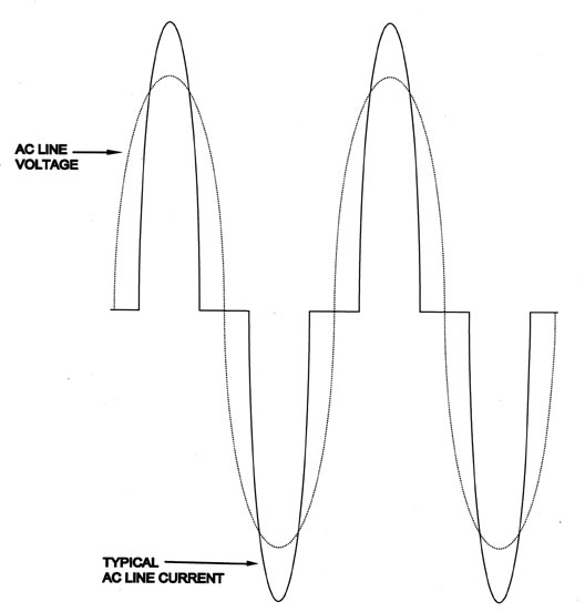 |
| Fig (1)The current consumption of an SMPS superimposed on the input voltage |
The Final Twist
Let’s face it, the dominant number of systems – commercial or military – are today energized by SMPS, and for the most part (in the USA) these supplies have no power-factor-correction. The topology of an SMPS (also known as Off-Line P.S.) requires that the input AC voltage be rectified and then filtered by relatively large capacitors (approximately 1000 microfarad per 1000W of output.) This rectifier-filter creates a poor power factor of 0.6-0.65 and very high peak currents for the charging of this capacitor. These current peaks occur at approximately the peak of the voltage sinewave, as can be seen from Fig. (1).
Repeated measurements under practical conditions show that in SMPS, the current peak to RMS ratio reaches a crest factor in the range of 2.5 to 3.5.
When a UPS is used to drive an SMPS, the following sequence of steps actually takes place. Within the UPS the input utility voltage is rectified and filtered to produce a DC rail. This DC-rail is then chopped to high frequency PWM pulses (class D configuration,) and then integrated and filtered to produce a highly regulated clean sinewave with total harmonic distortion of less than 5%. Much effort and expense is spent to produce this sinewave with such low distortion.
This voltage is then delivered to the SMPS (in the host system) as input. Within the UPS, it is then rectified again and filtered to produce a DC-rail just like the one in the UPS. Fig. (2) below shows this process, which at a glance seems rather wasteful (if not ridiculous.) The irony of it is that the majority of users insist on (and pay extra money) for pure sinewave voltage from the UPS, only to use it for apparatuses that rectify it. This apparatus (the SMPS) in the host system would have been better off if the input voltage was DC rather than AC.
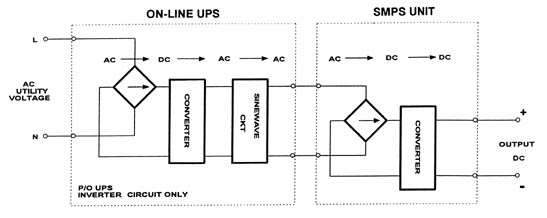 |
| Fig. (2) The power processing methodology when an On-Line UPS is feeding an SMPS |
DC UPS POWER SUPPLY
A DUPS is actually an SMPS with battery backup features. The backup is done either directly by a battery placed across the output of this SMPS or by a high frequency DC-DC converter imbedded within the SMPS. In any case, this system does not have double conversion when on utility, and no sinewave needs to be generated. The overall efficiency continuously (while on utility) is 75-80% (as opposed to 56-60% for UPS-MSPS combination.) More importantly, the overall price is only 10-20% more than the price of a standard SMPS. As such, back-up is obtained at a fraction of the cost of an AC UPS.
In DUPS, the battery backup may be accomplished in variety of ways – some very direct and easy, and some more complex. We shall now focus on these methods:
DUPS DESIGN METHODS
DUPS with LVBD
Often times an SMPS with a single output of 24V (military or communications applications) or 48V (Telecom applications) needs to be backed up by a battery for durations from a few minutes to a few hours. The output of the SMPS within this system is 24V or 48V, and this is the voltage which needs to be supplied by the backup battery if the utility fails.
It makes sense in these cases to connect the battery to the output of the SMPS, so if the utility (or the SMPS) fails, the battery could take over. Fig. 3 shows such a backup configuration. The problem, however, is that in this arrangement the battery may (in a lengthy blackout) be totally drained unless something stops it from doing so. This is the function of the LVBD (low voltage battery disconnect) circuit. In this scheme, the LVBD circuit uses a FET transistor (as a switch) to permit the discharge of the battery current into the load until the battery reaches a low (arbitrary, but in the range of 21-22V for 24V battery or 42-43V for 48V battery) threshold. At this point, the logic cuts off the gate drive to the FET and no further discharge is possible. Upon return of utility voltage, the circuit is reset immediately and the output of the MSPS is restored from utility. The battery is now charging from the SMPS output directly via the body diode of the FET. An “AC Fail” signal (a standard feature in most MSPS) is sent by the MSPS to the host system to notify it that output is now derived from the battery. Knowing the discharge time, the host system is programmed to shut down when the proper time arrives, and to do it without any crashes. This method is the simplest and least costly. It is also the most reliable and efficient. No battery energy is wasted for conversion, and charging is done simply from the SMPS output. These are the main advantages of the LVBD backup method.
On the other hand, the main disadvantage is that this method is suitable only to host systems that are characterized by the following type of SMPS unit:
A) The host system employs a single output SMPS of 12V, 24V, 48V, or some other battery standard voltage, (i.e., multiples of 12V).
B) The host system must be able to work well in the low to high battery range, which is ±10% of nominal. Whatever the battery type used, the load must tolerate its range. If the active circuitry in the host system needs tight regulation, this method is not applicable.
The battery should be relatively insensitive to the charging method and be tolerant of a high charge after a discharge. For this reason the use of maintenance free, sealed lead acid batteries is recommended. These batteries are rugged, tolerant and insensitive to charge. They are also inexpensive compared to all other types.
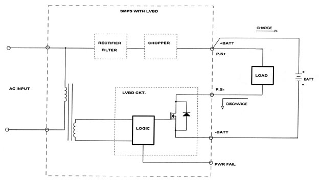 |
| Fig. (3) A DUPS consisting of a single output SMPS with LVBD circuit and external battery |
The battery is normally not contained in the SMPS, but within the host system. If a very long backup time is required, it can be packaged in a separate external cabinet.
A DUPS with Multi Output UPS
A more complex situation is encountered when the SMPS provides several outputs. In this case, it is not possible to place a battery (with LVBD) across the output, since only one output will be backed up and the rest will not. Fig. 4 shows the method of DUPS with a multi-output MSPS.
The DUPS accepts AC input from utility as well as DC input from battery. When AC power fails, a signal is delivered to activate a DC-DC Converter imbedded within the SMPS. This DC-DC converter produces 250-350VDC to replenish the DC rail, hence keeping the MSPS and all of its outputs alive. The activation of the DC-DC converter is quick (1-3 mS,) and this is well within the hold-up time of the MSPS. The large capacitors on the DC rail strore significant amounts of energy (with a high energy to volume ratio) due to the high voltage. Therefore, no extra storage is needed to facilitate a smooth, seamless transition between utility and the battery. All the outputs are never interrupted and the DC rail never falls off. Again, if the battery discharges to the threshold level, a shutdown occurs automatically. In this arrangement (as well as with LVBD) it is useful to give the end host system a “pending shutdown” alert signal, to advise that shutdown is imminent in 1-2mS.
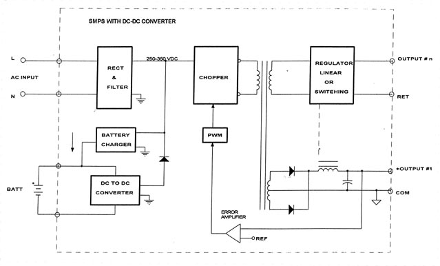 |
| Fig. (4) DUPD consisting of SMPS and internal DC-DC Converter |
The DC to DC converter, when designed to switch at high frequencies of 60KHz to 100KHz, measures 5” x 5.25” x 2” and weight less than 2 lb. As mentioned previously, the DC-DC converter remains inhibited when utility voltage exists, but is fired up automatically when utility fails. Therefore, normally, it does not dissipate any energy and the SMPS works strictly as a power supply. When the DC-DC converter operates, the unit as a whole works at 60-65% efficiency, as opposed to 50-55% in AC UPS combination. While an AC UPS dissipates power all the time (and is therefore costly to maintain during years of operation,) the DC-DC converter or LVBD circuits don’t dissipate any power in standby mode. This results in a saving of approximately $1000 in energy cost over a period of 5 years of continuous operation (in a case of 1KW load.) A comparison may be made between the DUPS and the AC Standby UPS which also does not dissipate energy in standby mode. However, there are profound differences which exist between the two which gives the DUPS enormous advantages: First, the DUPS makes use of the energy storage in the DC rail. This allows it time to transfer without interruption. Second is its high frequency operation, which gives it a size and weight advantage (as well as quick-start capabilities.) In these respects, the AC Standby UPS is not comparable to the DUPS because it will always suffer from interruption during transfer time.
With either the LVBD or DC-DC converter, the battery must be charged from the MSPS. A simple battery charging circuit can be designed for this function as an added output in the MSPS or as a small high frequency switching regulator. A rectified secondary voltage of the power transformer within the SMPS can produce a good charging voltage if regulated by an inexpensive 3 terminal linear regulator. The cost of components is barely $1.50 for a 1A charger working into 24V battery.
The DUPS design can be further simplified if the DC-DC Converter module is eliminated and an integrated design topology is used. Efficiency will not be improved in this approach, but cost and volume will.
DUPS WITH INTEGRATED TOPOLOGY
Consider that the DC-DC Converter circuit can share the same power transformer as the SMPS. Also consider a simple microprocessor circuit which controls all the functions of the SMPS. This controller senses the utility voltage and activates the power transistors of the converter stage. In this scheme there is only one power transformer, and as a result weight and volume efficiencies are increased and cost is decreased.
DESIGNING THE OPTION IN
For a quick implementation of a DUPS with or without an embedded DC-DC Converter, the following considerations must receive priority in the design stage. (Surprisingly, “designing in the option” does not cost anything except attention to the issue).
1. If only one output is needed, it should be as close as possible to the nominal voltage of a standard battery bank (i.e., 12V, 24V, 48V, etc.) This will make it possible to connect a backup battery at the output of the MSPS as long as LVBD circuit is included in it.
2. If the major output is suitable for DUPS with LBVD, and one more small output is needed, then it is cheaper to produce the second output by a small-encapsulated DC-DC converter driven from the main output or by a linear regulator using the main output as an input.
3. If multiple outputs are needed, consider the cost comparison between a number of small DC-DC converters driven from the main output (i.e., “distributed power” style) and a central DC-DC converter embedded module to facilitate DUPS configuration.
4. When you design an SMPS for a system, design it to accept input of either 115V/230VAC or 350VDC. Most SMPS in the market will accept 350VDC into their AC input terminals and will work just fine. (This is because the AC is being rectified anyhow). Do not include an AC fan or an auxiliary power supply (for housekeeping) which requires AC input in the design. This way, all that will be needed to implement a DUPS is 250-350VDC, which can come from a DC-DC Converter module to be located within or outside of the SMPS.
5. If possible, leave room inside the SMPS for the possible inclusion of a DC-DC converter module. Also offer the end user the option to buy the SMPS with the LBVD or DC-DC converter option from the very start, just in case he needs uninterruptible operation later. In case the end user initially elects to forgo the option and later decides he needs it, be ready to sell him a replacement drop-in SMPS with these features. Most end users will (with very little help) be able to replace the existing MSPS with one that is identical in size but includes DUPS functions.
PC Users Rejoice
For some time now, MSPS units with DUPS functions have been commercially available as drop-in replacements to the standard SMPS located within PCs. The DUPS is identical in size and features to the standard power supply inside the PC, except that it contains a DC-DC Converter module to facilitate DUPS. The batteries are contained (external to the SMPS) in a smartly designed, flat package which fits in one of the disk standard-slots. For approximately $150, the owner of a PC can replace the standard SMPS with a DUPS, or buy it from the factory already equipped with this unit.
SUMMARY
A stand alone AC UPS has its place in the complex world of electronics and utility power quality. However, with a good degree of pre-planning and a basic knowledge of all of the options that exist to provide battery-backup, the host system designer and end user should implement (or make it easy to implement) a DUPS. A 1 KVA On-Line AC UPS weighs 20 lb., consumes energy all the time and costs $1200-1500. A change to the existing MSPS to accomplish the same function adds 2 lb. and $500 to the standard MSPS, and what’s more, it saves energy continuously while providing a seamless transfer. It can be embedded in the host system SMPS and (most importantly) it does not have the incompatibility problem of the AC UPS. Actually, in the final analysis, a 1KW DUPS should be compared to a 3KW AC UPS because of the incompatibility issue. It is easy to see now that the final choice should be a DUPS
BIOGRAPHY
Aron Levy is the President of Technology Dynamics, Inc. and its Divisions Nova Electric and Mid Eastern Industries. He holds a B.S. degree from Long Island University and a Masters degree from Columbia University. Mr. Levy has published over 25 articles on power conversion subjects in technical magazines and conferences in the U.S. and abroad.