UNDERSTANDING (N+1)
part a: SINGLE SOURCE FAULT TOLERANT POWER SYSTEMS
by Aron Levy
Technology Dynamics Inc. Bergenfield, New Jersey USA
Often times users of power systems have an unclear notions regarding the configurations of power systems that provide features of redundancy, paralleling and the new notion of multiple source Fault Tolerant Power Supplies (FTPS). As a result, customers may specify a configuration that is beyond what is needed or intended, and hence increase the complexity and cost of the system. This article is the first segment in a series of 3 articles intended to cover all aspects of this topic from a user oriented point of view.
The general idea of fault tolerancy is to avert down time of the host system due to a failure of the power system. The cost of down time is nowadays too high and too complex to quantify, and it seems that no more justification is needed for the extra expense that redundancy imposes. Instead, fault tolerancy became a standard feature in the most telecom power systems, and information technology systems especially internet hosting setups.
REDUNDANT POWER SYSTEMS
The notion of constructing a fault tolerant power system from 2 or more paralleled power modules (PM), be it SMPS or DC-DC converters, targeted to provide redundant operation, is often mentioned as (N+1) configuration.
(N+1) Redundancy requires that a failure of any one (PM) in the power system, will not diminish the system’s ability of supplying full load performance to the host system. Accordingly, if the Redundant Power System (RPS) is made of 2 or more paralleled power modules, if one of these units fails, the other(s) must provide the host system adequate capability to perform to its fullest extent without any degradation. Further, the failure of a PM should not cause any disturbance in the DC bus beyond what can be tolerated. Therefore, unless notified (by an electronic signal) that one PM has failed, the host system will not detect the event.
However, it is almost impossible that when one PM in a redundant system abruptly fails , the common DC bus outputs will be free of any disturbance, or “glitch” as it is commonly referred to in the power supply lingo. A momentary drop or increase in the DC bus must be small enough and very quick so as not to upset the host system’s performance.
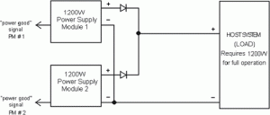
Figure 1 shows a (1+1) PM power system in redundancy. In this case the host system (i.e. the load) needs 1200W for full operation, and the chosen configuration is a made of two the1200W power supplies in parallel. Each one of these modules should be fully adequate to provide 1200W to the host system. Therefore any one-module failure will
leave the host system fully energized by the remaining module. If the host system requires 2400W, then the power system will require a third PM to be added in parallel for a setup of (2+1). Any 2 modules can supply the load needed.