Equipment used in critical applications must contain a power supply that is fault tolerant in order to guarantee continuous and uninterrupted functionality. The more critical the application, the more important is uninterrupted functionality. This paper focuses on the importance of system power with immunity to single or multiple failures and it describes the various architectures of uninterrupted power equipment with backup and redundancy. It offers system designers and reliability professionals a range of possibilities to serve this objective on a practical level, and with a minimum cost impact. Knowing the options to formulate a fault tolerant power systems (FTPS), will enable cost savings while at the same time reduce complexity and enhance reliability. Most importantly is to realize the fact that solid state FTPS have limitations which must be considered carefully in order to avoid severe compatibility problems when used with the system.
The paper discusses AC and DC UPS, N+1 redundancy, “hot swap” concept, and backup methods, it makes the case for DC UPS.
It is widely accepted that the highest stresses in any electronic system is mostly in its power supply. This is where most of the power losses exist, and therefore the highest thermal stress. The input derived from the utility (or a generator) is subject to fluctuations, brownouts, transients and interruptions. The power components in the power supply are switched at high speed while conducting high current or subjected to high voltages. Further the switching speeds are ever increasing in order to reduce volume and weight. This switching results in conducted and radiated noise which increases exponentially with power level and as a result often contaminate logic and control circuitry in terms of stability and operation.
All of these factor make the power supply of any electronic system the most vulnerable to failure, resulting in total system dysfunction. This is therefore the main reason for designing the system with backup features which permit uninterrupted power delivery despite one or more failures in the utility or power processing path.
The Concept of Fault Tolerant Power Systems
In the ultimate case an FTPS is a power supply (with DC or AC input or output) which delivers uninterrupted output(s) to equipment (or functional circuits) despite one or more of the following detrimental events:
- A failure of the input power source (utility or generator)
- A failure of the power supply itself
- A failure of the battery used as a back-up energy source within the backup apparatus.
Critical systems which cannot tolerate power supply failure exist in every filed. In some, the failure will entail a crash of the system with possible loss of data, but in others it may cause a dangerous disruption resulting in loss of life, crash of a vehicle, loss of valuable specimen, or loss of defense or attack capability in a military situation. The following are examples of such applications:
In the medical filed
- A blood analyzer machine
- Operation room equipment
- Dialysis machine
- Hospital Ward as a whole
In the IT filed
- Data centers
- Servers
- Personal computers
In the Military filed
- Radar systems
- Fire safety equipment on a ship or submarine
- Navigation systems
- Electronic detectors systems
- Communication systems
In Telecom
- Communication apparatus
- Internet Service
- Phone Service
- 911 service, and contact with first responders
In Utility
- Control room equipment
- Servers
- Data feeds
In Nuclear Reactors
- Control systems
- Monitoring devices
- Emergency systems
- Post natural disaster
In all of these failure circumstances the functionality of the power system is impaired and as a result the host system is disrupted. Installing backup entails added expense, and hence needs to be carefully considered in a context of cost benefit analysis. In the ideal situation no backup is needed since the loss just causes inconvenience. On the other hand no price is to high when loss of life is considered, or when large monetary losses will happen such as if trading is halted suddenly in a busy stock exchange. We shall now consider backup measures from the simplest to the most complex to implement. Higher complexity usually means higher cost.
Backup for Utility Loss
Even in advanced well developed countries (in terms of infrastructure and technology) the utility grid is prone to fail from time to time. This happens due to equipment failure or from severe weather impact or natural disasters. The disruption can be short (one cycle or less) or long (minutes, hours or days). These type of disruptions require a power system that has a well thought out plan how to endure the power outages. Here are the important factors at play:
- Most electronic systems can ride through one cycle of input utility loss, because of energy stored in internal capacitors within the switching power supply that drives the system. This is called “holdup time” capability, and it means that for such a duration, the switching power supply is able to deliver full load and remain in regulation despite the one cycle input voltage disruption
- For interruptions which are longer in duration than one cycle additional stored energy is needed. Here the common solution used universally is to put a stand-alone backup unit between the utility outlet and the system being backed up. This apparatus commonly named UPS (uninterruptible power supply) contains a battery bank which is sized for the duration of the desired backup considering the magnitude of the load.
- Most UPS systems with battery backup are not made for disruptions exceeding 15 minutes. Some however can deliver uninterrupted performance for up to 24 hours. After the Fukushima Tsunami disaster, nuclear power stations were required to provide 24 hour backup to some critical equipment as an emergency survival period. Such a backup can still be done by a battery bank stored in a large cabinet. However, in a case of a hospital, airport control tower, Radar station or a data center, it is not practical to implement the backup by battery alone. Here a hybrid system may be used with short term battery backup and long term Generator backup. The load is run on a high power UPS which provides minutes of backup while a generator is turned on automatically upon utility loss. Once the generator is running the load is switched to it automatically, and then back to the UPS and eventually the utility. All these transfers can be done back and forth by SST (Solid State Transfer) switches which enable seamless transition with no disruption at all or less than in the worst case ¼ cycle duration.
- To accomplish seamless transfers the UPS needs to adapt itself to the utility or the generator by synchronizing to them in terms of frequency and phase. In military systems which are run field on generator and have no connection to commercial utility, a solid state UPS is used to provide up to 15 minutes of backup while the generator is refueled. Once the generator is running again the load is transferred back to it and the UPS runs unloaded until the next event of generator failure or refueling.
A key element in every UPS design, and this includes the cheapest standby UPS intended for personal computers are the following important features:
- The UPS conditions the utility voltage and delivers to the load a voltage free of spikes, transients and fluctuations. This is particularly important in countries such as India where utility voltage fluctuations are frequent and significant. The nominal 230V 50Hz nominal utility in some countries drops to below 80V and may reach 300V as an upper limit. The UPS delivers to the load well protected (from lightning or utility transients) and regulated voltage and frequency. This in itself is of great value to any electronic system in addition to the backup function.
- The UPS reports to the load when utility is lost and when it comes back. While running on battery it reports the state of charge of the battery to enable the user to gauge the amount of running time left on battery. This reporting is done via RS232, RS485, http, SNMP, CANBUS or some other protocols which the system is programmed to accept. SNMP is used for most secured military systems, or out of reach of internet. The UPS provides a signal to the load to warn it that it is about to turn off in a preset time. This is done to allow the system to shut down in time. This communications feature is of great importance to the users, and if is done via the internet it allows remote monitoring of the UPS at all times. Further, the UPS can send Build In Test (BIT) data on its operational conditions, thus alerting the user or the maintenance center of pending failures such as to fan failure, excessive temperature buildup or some loss of functionality.
UPS Systems the Mainstay of Utility Failure Backup
Stand Alone UPS
Fig (1) shows a stand-alone UPS box located between the AC utility and a system which requires uninterrupted input power usually for a limited time between a few seconds and 24 hours.
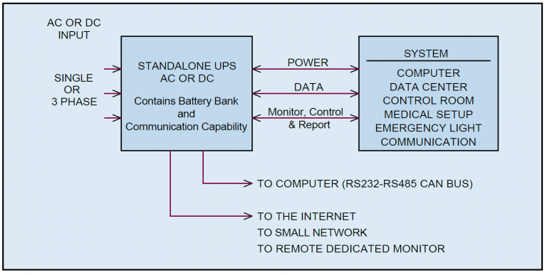 Fig. (1)
Standalone UPS inserted between the utility and the system.
The main advantage of such a UPS is that it is a stand-alone unit which can be added at any time between the utility and the system. As such it can be an optional add-on to an existing system. The system manufacturer may leave the decision to the end user if to back up the system at their expense. When a UPS is used, if the type known as ON-LINE UPS (as opposed to “standby” UPS) is chosen, the transfer from utility to internal battery is instant and seamless. Often the system is actually running from processed and conditioned power and not directly on the utility. This produces the added advantage of stable, clean stabilized and transient free input delivered by the UPS to the system. This enhances the system performance and protects it from the fluctuations of the utility.
Types of UPS – A system which can tolerate one cycle drop of the utility fails can use a “Standby UPS” which is smaller and cheaper. With such an UPS type the system is actually running on utility while utility exists, and is transferred to backup mode only when utility fails. When utility exists, the UPS is 100% efficient. The transfer needs to be accomplished usually by a relay in one cycle i.e. 16mS for 60 Hz system or 20mS for 50 Hz system. Standby UPSs are inexpensive and small in size. They are commonly used by consumers to back up their personal computer. Having said this, some standby UPS contain conditional circuitry, transient protection and EMI filters. Most if not all can deliver to the user useful information on the condition of the battery. All standby UPS provide audible alarm that utility failed and the load is on battery.
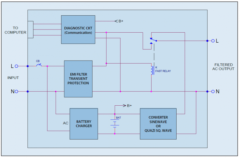 Fig. (2)
AC Standby UPS. This is the most common low power UPS used by consumers to back-up personal computers.
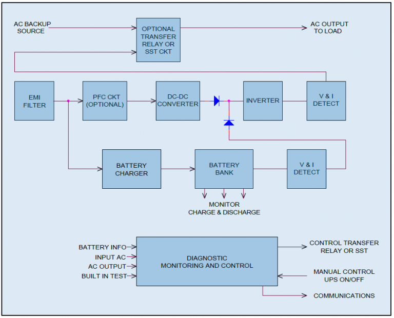
ON-LINE UPS – This is the common type used for critical application since the transfer offered by this type is seamless and it feeds conditioned power to the system at all time. In an on-line UPS the utility voltage is converted to DC first and then synthesized back to sine-wave. The battery in such UPS should be adequate for full load backup for desired backup time from a few seconds to a few hours. The conditioning of the utility power, inclusion of EMI filter and seamless transfer, make the ON-LINE UPS the choice for high-grade, critical mission and military systems. ON-LINE UPS can range in power from 500 W for a small system to over Megawatts for a data center plant. Fig. (2) shows the building blocks of typical UPS.
Fig. (3)
The building blocks AC UPS

Fig. (4)
One AC UPS with back-up feed which takes over in case of failure.
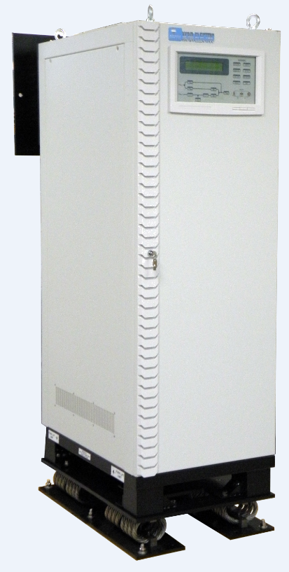
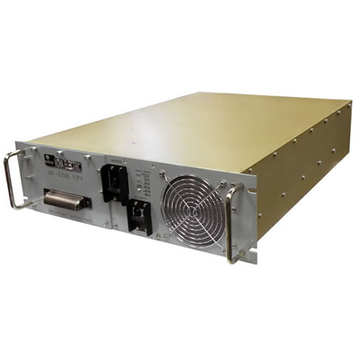 Nova Electric – Ultralight rack mounted 3KW UPS with retractable battery
Fully qualified UPS to MIL-STD-461, MIL-STD-1399 and MIL-STD-810
 Nova Electric – Jupiter series
UPS 10KW to 450KW with bypass source and SST
Used in radar systems and naval ships
Things to remember – It is essential to keep in mind the following while considering the use of a UPS to back up the system against loss of utility.
- The UPS is an electronic device, not a generator, hence it should be rated carefully for the type of load that the system present to it. If the system presents a non-linear load such as a power supply without power factor correction (PFC), the UPS needs to supply high current pulses, and hence should be rated at higher power. A good rule of thumb is to double the power rating compared to power factor correct load. The same applies to laser printers which consume current in high pulses. Motors also have very high starting current.
- Most electronic systems contain switching power supplies with energy storage capacitors. When such systems are turned on, there will be a high inrush current pulse. The turn on inrush is 3-10 times. It will cause the UPS to sense abnormal load condition, or even interpret it as a short. The UPS will instantly react by shutting itself down. This turn-on inrush current high pulse must be considered when specifying or rating the UPS. Otherwise the UPS output will collapse every time the system is turned on. A good rule of thumb is to rate the UPS three times the system full load power.
- Systems containing motors, compressor or any air condition apparatus as a whole, will draw upward of 5 times input current when the motor starts, or the compressor kicks in during its cycling. As a rule of thumb the UPS needs to be rated five to ten times the normal load.
- Some loads like motors when started and stopped abruptly, send energy back to the input source. This can be very substantial energy (known as back EMF) which can cause the UPS instant failure if no provision to absorb it exists. The usual failure of the UPS is the destruction of its output stage due to excessive voltage buildup caused by the backup. It is therefore not advisable to use electronic UPS when back EMF exists. The case is easier for DC UPS since a large capacitor bank (made for instance of super caps) can absorb the back EMF to a safe level. In electric cars, the back EMF when the car slows down or stopped is used to charge the battery. Thus it is put to good use. Not so the case with UPS.
In conclusion, the stand alone UPS (AC or DC) offers limited time replacement to the utility when utility power fails or drops to below brownout level. Successful use of a UPS depends on considering the static and dynamic profiles of the load. Non-linear characteristics of the load, high inrush current at turn-on and motor or compressor loads require much higher power rating for the UPS. Failure to understand these load related factors will result in a deployment of a UPS which is unsuited to work with the given system.
DC UPS Reviewed
A DC UPS like its AC counterpart keeps the input voltage to the system intact when the input source fails. The backup is temporary and it depends on the internal or external battery used as alternative energy source. Backup time of 5-15 minutes are common, but in case of electric utility control room or a nuclear reactor it can be 24 hours.
If a system is driven from 24 V (common to vehicular applications), 48 V (common to telecom systems), or 120 V (common to utility control room), a DC UPS containing internal or external (or both) batteries can provide the necessary backup in an efficient and much simpler circuit than an AC UPS.
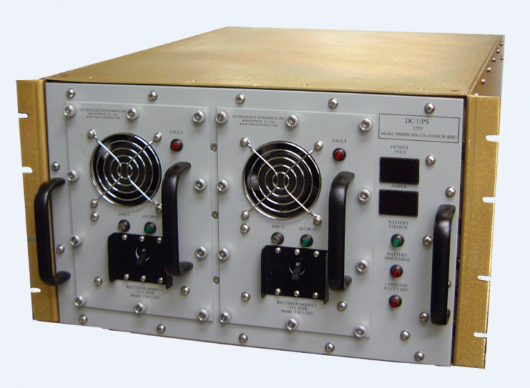
 Technology Dynamics Inc. – DC UPS with redundancy
The main building blocks of a DC UPS are the backup battery, the battery charger, the input sensing circuit, and a mechanism to cut off from the battery when it reaches a low threshold. These are simple building blocks that contribute to a simple, higher reliability and lower cost backup system. The main attributes of a DC UPS are:
- Simplicity that manifests itself in higher reliability and lower cost.
- Low sensitivity to loads that have high turn on current or periodic high current pulses.
- No issues with non-linear loads. No issues with reactive loads.
- High running efficiency
- Easy to deal with back EMF by a simple capacitor bank (using electrolytic capacitors or super caps) at the output.
Keep in mind however that DC UPS are meant to backup systems which run from DC input, and for the most part 12, 24, 48 or 120 VDC inputs. The vast majority of electronic system however accept AC, not DC input.
Fault Tolerance by Redundancy
Redundancy is a configuration where the power system is built per the (N+1) principle. This means that multiple (minimum two) power supplies are to be used in parallel to drive load, in a way that one power supply failure will not diminish full rated power to guarantee full functionality. For instance if the load (which may be an electronic system) requires 2 KW power supply, this can be satisfied by two power supplies each rated 2 KW or 3 power supplies , each rated 1KW, or 5 power supplies each rated 500W. Any one power supply failing will leave the 2 KW needed for full functionality of the system.
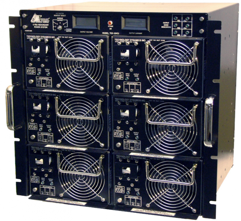 Technology Dynamics Inc. – 6 Modules (5+1) Redundant Power Supply
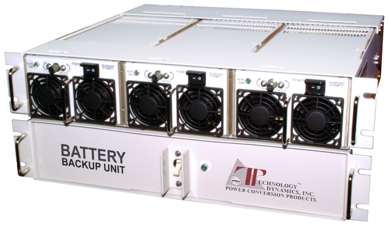
 Technology Dynamics Inc. – Redundant military shipboard rectifier with external battery for backup
Redundancy of the Battery
An AC or DC UPS is used as we have seen to back-up the utility or the generator. But what happen if the UPS itself fails due to component or battery failure. Such a situation can happen and the most immediate solution will be to connect another UPS in redundancy. This will also require a transfer switch (solid state or electromechanical) to switch the load from the failed UPS to the one backing it up. The down side of this scheme is doubling the cost of the back-up system, but that may not matter if the cost of failure and therefore lack of backup is significantly higher. The upside however is that the second UPS can pick-up at the end of the battery capacity of the first one and hence double the backup time.
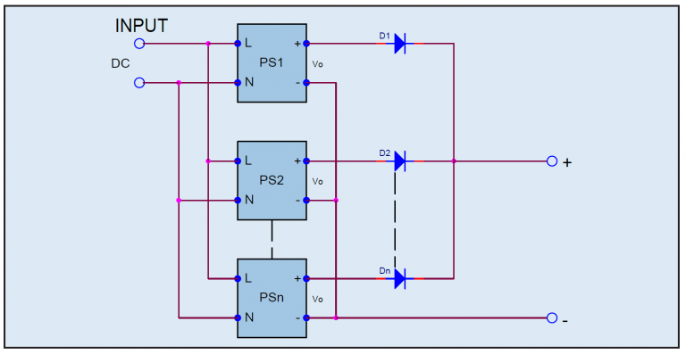 Fig. (5)
Redundant (N+1) DC Power System.
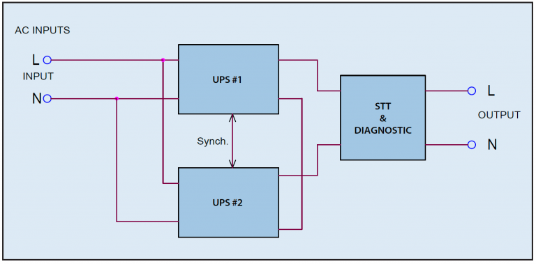 Fig. (6)
AC UPS redundant system with solid state transfer switch.
There are other concepts to consider:
- It is most desirable that the ON-LINE UPS is able to transfer the load to the input utility if it fails or its battery becomes defective. Such a feature allows the user to replace the UPS or the battery while the load is energized from the utility. In this scenario, the UPS that failed should be designed to switch automatically to the utility and notify the user via communication (RS232, RS485, CANBUS, SNMP, http) that a failure took place and high risk is present due to lack of backup is the utility fails.
- In super critical situations (such as security system of a bank or an incoming missile detection system), the viability of the battery has to be checked and verified at all times. Backup systems are installed with high expectations but the battery in itself has limited life and may be subject to deterioration over long time especially if it is located in a place which has elevated ambient temperature as battery service life is exponentially reduced by its temperature.
Testing the battery general viability or specifically its state of charge (SOC) is required in such applications. Yet measurement of SOC of Lead Acid batteries is rather difficult, so most designers opt to measure the battery voltage under load as a way to determine if the battery is maintaining good capacity. Nova Electric has developed a circuit which load the battery for 100mS during which the battery voltage is measured and recorded.
The test is repeated at predetermined intervals ranging from once every 10 seconds to once per day or per week. The readings are then compared to a reference battery or to manufacturer criteria to determine if the battery should be replaced.
- Battery redundancy within the UPS itself can eliminate the major functionality due to battery deterioration.
Conclusion
Critical applications such as military, medical, banks and laboratories, cannot tolerate interruption in functionality due to utility or power system failure. Therefore fault tolerant power systems are used. Such systems that bridge over utility failure are the AC or DC UPS which contain batteries as reserve energy source. To guarantee non-stop functionality despite power supply failure, redundant power systems connected in (n+1) configuration are used. Long term backup for utility failures deploy UPS and generator in a hybrid power system.